
Load Cases Hold Your Constraints and Loads
A load case is a named set of constraints and loads, and every constraint and load belongs to one. Start with load case 1, and add more with the plus next to Load Cases in the layer tree. Running several load cases lets you test the same geometry under different conditions.
Add a Constraint
Click Constraint in the toolbar. In the Add Constraint panel:
- Type: choose the constraint. Options include a fix displacement that locks chosen axes (X, Y, or Z), a symmetry constraint, and a roller constraint.
- Name: label it so you can find it in the tree.
- Load case: apply it to all load cases (shared) or to a specific one.
Enter the values the type needs, for example the fixed axes for a fix displacement, choose where it acts with the selection tools, then click Add.
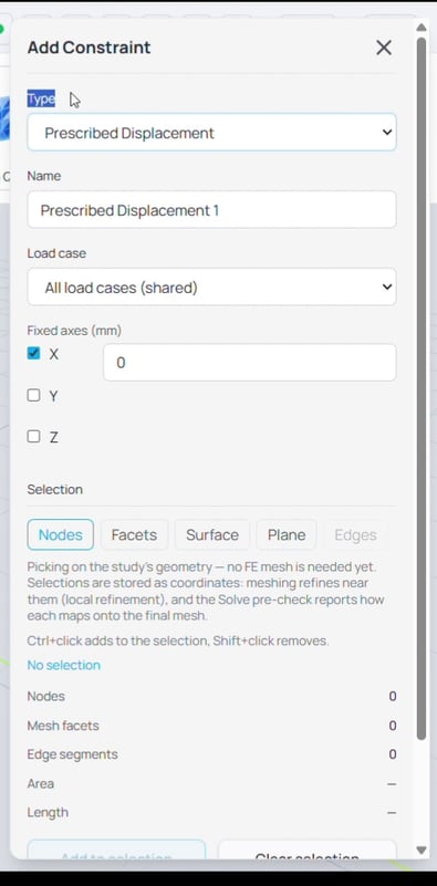
Figure 1. The Add Constraint panel: type, name, load case, per-axis values, and the selection tools.
Add a Load
Click Load in the toolbar. The Add Load panel works the same way:
- Type: for example a surface traction or a point load.
- Load case: which load case the load belongs to.
- Input mode: how the force is expressed, for example total force, force per unit area, force per length, or per-node force, depending on the load.
- Force components/values along X, Y, and Z, and how much force or force density is.
Choose where the load acts, then click Add.
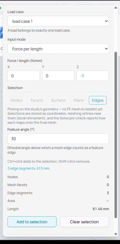
Figure 2. The Add Load panel: type, load case, input mode, and force components, with selection below.
Target Constraints and Loads With Selection
Both panels share the same selection tools. Pick a selection mode, select on target features in the geometry, and use Add to selection. Ctrl-click adds to the selection and Shift-click removes. Selections are stored as coordinates, so you do not need a mesh yet. Meshing later refines near them, and the solve pre-check reports how each one maps onto the final mesh.
- Nodes: individual points on the geometry.
- Facets: individual surface facets.
- Surface: flood-fills across a face. Threshold angle controls how far the fill spreads across curvature, and Max distance limits how far it travels, where 0 means unlimited.
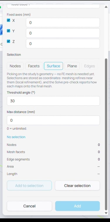
Figure 3. Surface selection flood-fills a face, bounded by a threshold angle and a maximum distance.
- Plane: selects everything on a cross-section. Pick an axis, set the position along it, and use Tolerance to set how thick a slice counts as selected.
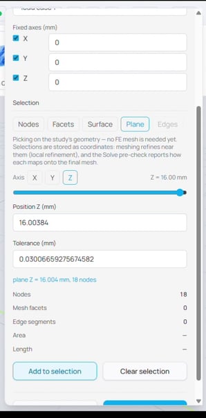
Figure 4. Plane selection captures a cross-section, here 18 nodes on the top face by axis, position, and tolerance.
- Edges: selects along edges, using a Feature angle that sets the dihedral angle above which an edge counts as a feature.
Tips: Target geometry for assigning constraints and loads can also be the generated mesh. Turning on the view of target mesh can select features from it to assign constraint and load.
Work Across Load Cases
As you add constraints and loads, they appear under their load case in the tree. A shared constraint shows in every load case. This is how you build, for example, a fixed support that holds the part in every case, with a different load in each.
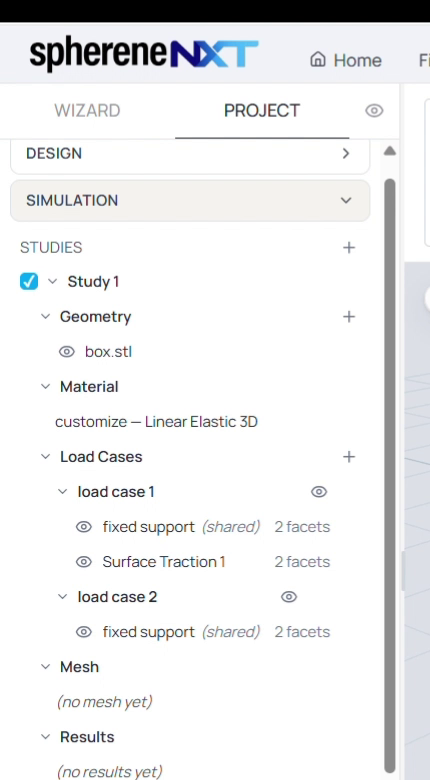
Figure 5. Two load cases in the tree. The fixed support is shared across both, while the surface traction belongs to load case 1.
Quick Reference
|
Action |
What it does |
Where to find it |
|
Constrain |
Opens the Add Constraint panel |
Toolbar |
|
Load |
Opens the Add Load panel |
Toolbar |
|
Type |
The kind of constraint or load |
Add panel |
|
Load case |
All load cases (shared) or a specific one |
Add panel |
|
Nodes / Facets |
Select points or single facets |
Selection |
|
Surface |
Flood-fill a face by threshold angle and max distance |
Selection |
|
Plane |
Select a cross-section by axis, position, and tolerance |
Selection |
|
Edges |
Select edges by feature angle |
Selection |
|
Add to selection |
Confirms the picked region |
Selection |
|
Plus next to Load Cases |
Adds another load case |
Layer tree |
| Previous Article | Next Article |
| sphereneNXT Simulation (Part 2): Assigning Materials | sphereneNXT Simulation (Part 4): Meshing and Mesh Quality |