
Before You Dive In
Surface bias lives right next to Cell Parameter in the icon row above your 3D viewer, and it's worth a look once your cell size is dialed in. Rather than changing how dense your structure is, surface bias shifts the minimal surface itself toward one side or the other, opening channels on one side of the generated infill surface while tightening them on the opposite channel. This can be quite practical sometimes in fluid applications such as heat exchangers. It's a small parameter with a big visual effect, so this article walks through what it does, shows both extremes side by side, and covers how to vary it across different parts of your model.
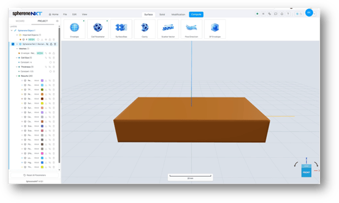
Surface Bias sits between Cell Parameter and Cavity in the icon row above the 3D viewer.
Opening the Surface Bias Panel
Click the Surface Bias icon and the Define Surface Bias panel opens. By default, the Choose Input Method is set to Surface Bias Constant Value, with an empty field waiting for a number between -1 and +1.
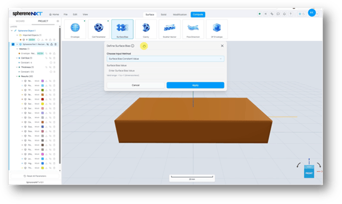
The Define Surface Bias panel. The valid range for Surface Bias Value is -1 to +1.
Tip: Surface bias is dimensionless, and 0 is neutral. If you never touch this parameter, sphereneNXT treats it as 0 and builds your structure with no shift applied at all.
Three Input Methods
Just like Cell Parameter, Choose Input Method gives you three ways to set surface bias: a Constant Value applied everywhere on your envelope, a Point Map for varying the amount across different areas, and Import from File if you already have values ready to bring in.
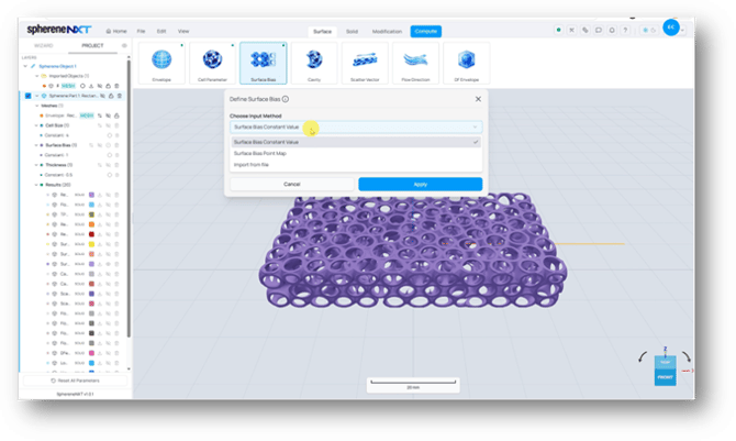
Choose Input Method expanded: Surface Bias Constant Value, Surface Bias Point Map, and Import from file.
What Surface Bias Actually Does
Surface bias shifts sphereneNXT's minimal surface toward the positive or negative direction along its surface normal. That shift changes the size of the chambers sitting on either side of the surface, opening one set up while shrinking the other one down.
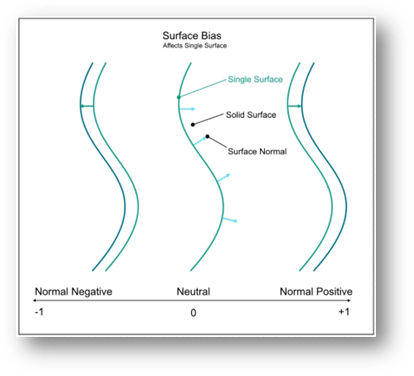
Surface bias shifts the minimal surface along its surface normal, from -1 (fully negative) through 0 (neutral) to +1 (fully positive).
Tip: The full -1 to +1 range is useful mainly for seeing the effect clearly. In practice, smaller values usually give you a more usable result, since the extremes push the geometry to its limits.
To show just how much surface bias can move your geometry, here's the same envelope and cell size computed at surface bias -1 and again at +1.
Setting Surface Bias to -1With Choose Input Method set to Surface Bias Constant Value, type -1 into the Surface Bias Value field, click Apply, then name your output and compute.
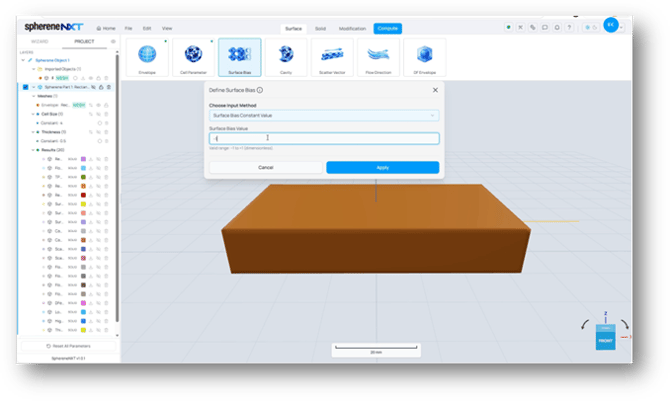
Typing -1 into the Surface Bias Value field.
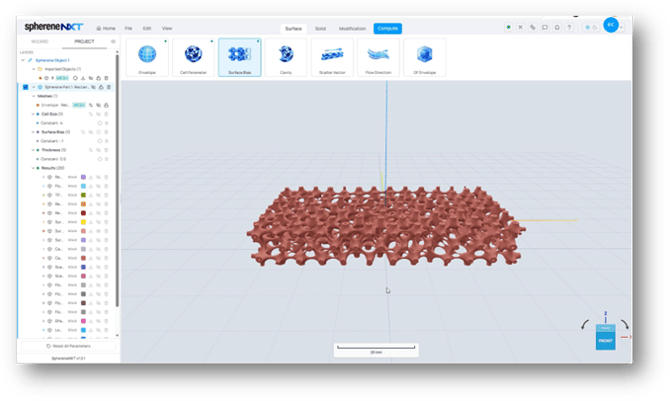
The result at surface bias -1. One set of channels has shrunk down almost completely, while the other has opened.
Setting Surface Bias to +1Open the Surface Bias panel again, switch the value to 1, apply, and compute a second time.
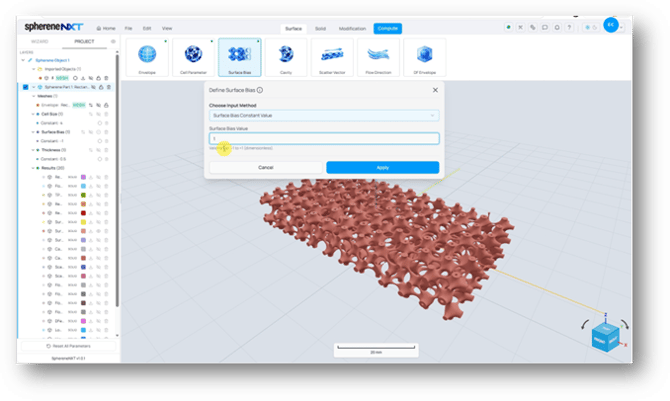
Typing 1 into the Surface Bias Value field, with the -1 result still visible behind the panel.
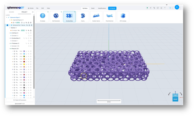
The result at surface bias +1. The channels that shrank before are now the ones that have opened up, and vice versa.
Tip: These two examples sit at the extreme ends of the range on purpose, to make the effect obvious. Somewhere between -1 and +1 is usually where you'll land for a real project.
A constant value applies to the same shift everywhere on your envelope. If you want different amounts of bias in different areas, switch Choose Input Method to Surface Bias Point Map instead.
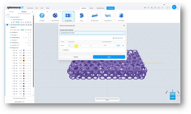
Surface Bias Point Map, with a table for adding points and a Pick button for placing each one in the 3D viewer.
- Add a row for each point you want to control, using Add More.
- Enter a Surface Bias Value between -1 and 1 for each point.
- Click Pick, then click on a location on your geometry in the 3D viewer to place that point.
Turning on Your Envelope's Visibility First
You can't pick a point on the computed result or the mesh output, only on your original geometry. Before you start picking, make sure your envelope visibility is switched on in the layer panel, or Pick won't have anything to click on.
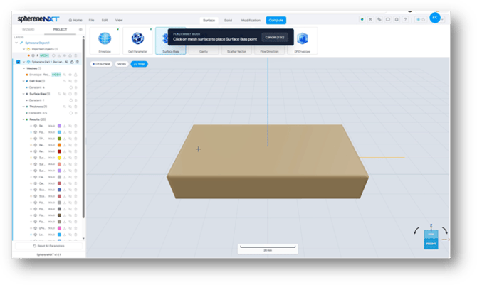
Placement mode active, with the envelope's visibility switched on so its surface can be picked in the 3D viewer.
Tip: If clicking in the viewer doesn't seem to register a point, double check that your envelope's visibility is turned on. It's the most common reason picking doesn't work.
Once your points are placed and each one has a surface bias value assigned, click Apply and compute to see the result. Different areas of your structure will shift by different amounts, based on where you picked and what value you gave each point.
Quick Reference
A cheat sheet for everything covered above, in case you just need a quick reminder later.
|
Option |
What It Does |
Where to Find It |
|
Surface Bias Constant Value |
Applies one bias amount, from -1 to +1, across your entire structure. |
Choose Input Method |
|
Surface Bias Point Map |
Let's you pick different points on your envelope and assign each one its own bias value. |
Choose Input Method |
|
Import from File |
Imports bias values from a file instead of picking points manually. Points with a value out of the range of TPMS options-1 to 1 will be skipped. |
Choose Input Method |
|
Surface Bias Value |
The amount of shift applied, from -1 (fully negative) to +1 (fully positive). 0 is neutral. |
Define Surface Bias panel |
|
Envelope visibility |
Needs to be switched on before you can pick points for a point map. You can't pick the computed result. |
Layer panel |