
Scatter Vector can stretch your ADMS structure locally to align its stiffness with load paths, giving you directional reinforcement along principal stress paths.
You can use a constant value to stretch your entire structure the same way everywhere. Or when you use a point map to pick specific points and assign different scatter vectors, a smooth gradient of scatter vector will be mapped based on defined points, which defines the local stretching of generated infill structure at different locations.
Tip: Scatter Vector enables stretching ADMS structure, while TPMS uses another stretching function for the same purpose.
Opening the Scatter Vector Panel
Scatter Vector sits in the icon row between Cavity and Flow Direction. Click on it and sphereneNXT shows you a short description before the panel settles in.
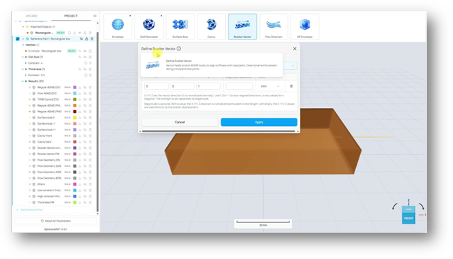
Define Scatter Vector: vector fields stretch ADMS locally to align stiffness with load paths, with directional reinforcement along principal stress paths.
The Define Scatter Vector panel defaults to Constant Scatter Vector, with X, Y, and Z fields, an optional Magnitude field, and a Units dropdown set to mm.
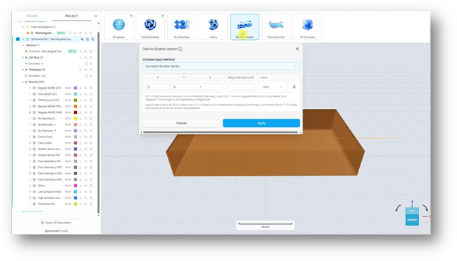
The Define Scatter Vector panel, freshly opened. Z defaults to 1, Magnitude left blank, Units set to mm.
If the magnitude is not given, X/Y/Z of the scatter vector defines both the direction and length of the stretching for the ADMS structure. Else, magnitude defines the length of the stretching, and the X/Y/Z of scatter vector only denotes the direction of stretching.
Setting a Constant Scatter Vector
Say you want your structure to stretch along the X axis. Set X to 1, leave Y and Z at 0, and give Magnitude a value, for example 2mm. That tells sphereneNXT to stretch the structure 2mm in the X direction.
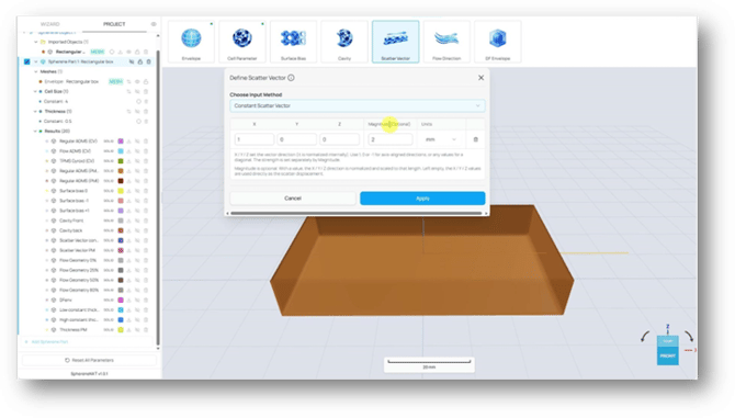
X set to 1, Y and Z at 0, Magnitude set to 2, Units set to mm.
Apply, then Compute as usual. Output Type still shows the same four options: Single Surface, Solid Surface, Halfspaces, and Chamber.
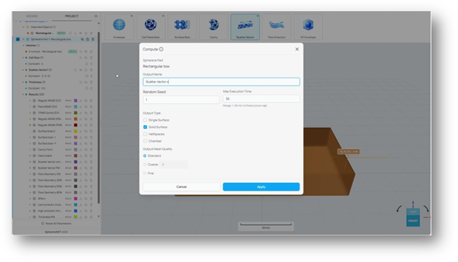
The Compute dialog. Output name set to Scatter Vector constant, Solid Surface selected.
Once it's finished, the result shows your whole structure stretched evenly in the direction you chose:
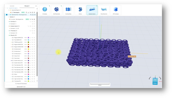
The result of a constant Scatter Vector in X at 2mm magnitude. The whole structure stretches evenly in that direction.
Stretching in Different Directions with a Point Map
A constant value stretches everything the same way. If you want different areas of your structure pulling in different directions instead, for example one side reinforced along X and another along Y, switch to a point map. Open Define Scatter Vector again and expand Choose Input Method. You've got three options here: Constant Scatter Vector, Scatter Vector Point Map, and Import from file, the same pattern you've already seen on Surface Bias.
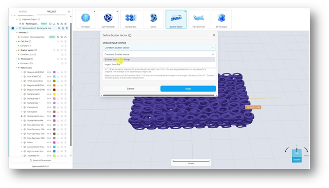
Choose Input Method expanded: Constant Scatter Vector, Scatter Vector Point Map, and Import from file.
- Scatter Vector Point Map lets you pick your own points directly on the geometry and set a direction and magnitude for each one.
- Import from file brings in a ready-made CSV of point data instead, handy if you already have one from elsewhere. But the CSV file for scatter vector should have six or seven values per row. These values represent the X/Y/Z coordinate of the point, the X/Y/Z of the scatter vector, and the magnitude, respectively.
Select Scatter Vector Point Map and the panel switches to a table: Points, Coordinates, Scatter Vector Value, Magnitude, and Units, with a Pick button on each row and an Add More button underneath.
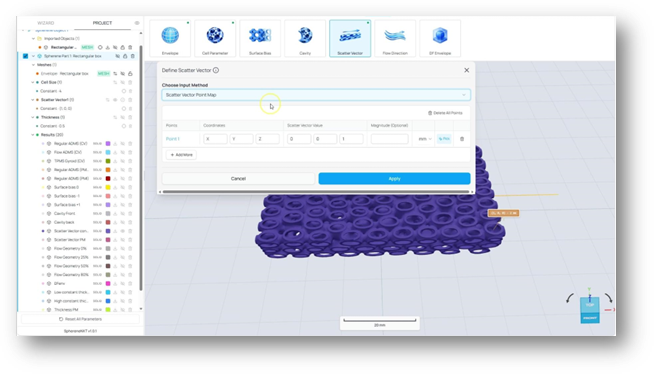
The Scatter Vector Point Map table, with Point 1 ready to pick.
Tip: Turn on the envelope visibility before you try to pick points. You need to see the geometry by clicking on the location.
Click Add More for a second point, then pick each one directly on your geometry, one in the area you want reinforced along X, another where you want Y instead. For this example, point 1 gets a Scatter Vector Value of (1, 0, 0) with a 2mm magnitude, and Point 2 gets (0, 1, 0), also at 2mm.
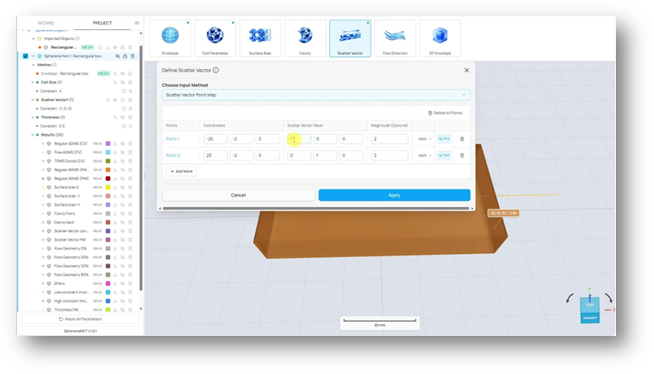
Two points were picked on the envelope. Point 1 set to (1, 0, 0) in X, Point 2 set to (0, 1, 0) in Y, both at 2mm.
Applying a point map on top of a constant value you've already set triggers a quick confirmation, since it replaces what was there before.
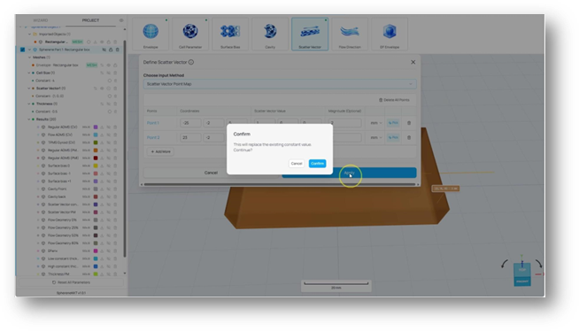
Confirm dialog: this will replace the existing constant value.
Confirm, then Compute and give it a name, for example Scatter Vector Point Map applied. The layer tree confirms both points and their coordinates once it's set.
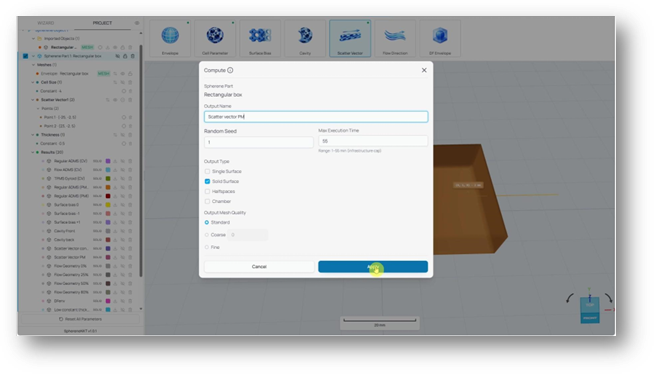
The Compute dialog, with Points (2) and both sets of coordinates visible in the layer tree on the left.
Once the computation finishes, you can see both directions at once, each point pulling the structure in its own way, blending smoothly with no hard seam in between.
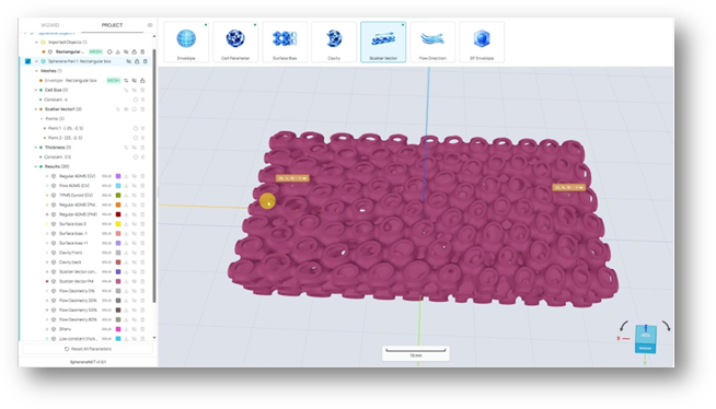
The point map result. The (0, 1, 0) point stretches its area in Y, the (1, 0, 0) point stretches its area in X, and the two blend together with no sharp edges in the middle.
This kind of smooth blending between completely different local directions, with no visible transition line, is one of the things sphereneNXT's underlying geometry does especially well.
Quick Reference
A cheat sheet for everything covered above, in case you just need a quick reminder later.
|
Step / Option |
What It Does |
Where To Find It |
|
Scatter Vector icon |
Opens the Define Scatter Vector panel. |
Icon row, between Cavity and Flow Direction |
|
Choose Input Method |
Constant Scatter Vector, Scatter Vector Point Map, or Import from file. |
Define Scatter Vector panel |
|
X, Y, Z fields |
Sets the direction of the stretch vector. Its length represents the stretching length when the magnitude is blank. |
Define Scatter Vector panel |
|
Magnitude (Optional) |
Sets the strength of the stretch. If not blank, the length of the X, Y, Z fields will be ignored.
|
Define Scatter Vector panel |
|
Scatter Vector Point Map |
Lets you pick individual points on the geometry and assign each one its own direction and magnitude. |
Choose Input Method |
|
Pick |
Assigns a table row's coordinates from a location you click directly on the geometry. |
Scatter Vector Point Map table |
|
Add More |
Adds another point to the table. |
Scatter Vector Point Map table |