
Flow Direction lets you control the way your ADMS structure flows in a specific direction. It was built with fluid applications in mind, mainly heat exchangers, heat sinks, and cold plates, where the goal is to reduce pressure drops as much as possible while keeping heat dissipation high. But it can also introduce directional preference into the infill structure, which can be useful for mechanical applications such as aesthetic or artistic designs. You can use it in any project you're working on.
Tip: Applying Flow Direction switches your structure to Flow ADMS automatically, even if Cell Parameter is still set to Regular ADMS. You don't need to change that setting yourself first.
Opening the Flow Direction Panel
You'll find Flow Direction sitting in the icon row, right after Scatter Vector. Hover over it and sphereneNXT tells you exactly what it does before you even click.
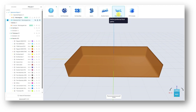
Flow Direction in the icon row. The tooltip reads: define preferred fluid paths.
Click on the Define Flow Direction panel opens. Just like Scatter Vector, it comes with a Choose Input Method dropdown, defaulted to Constant Vector, with X, Y, and Z fields underneath and an optional Magnitude field on the right.
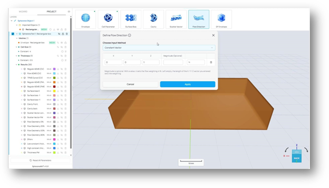
The Define Flow Direction panel, freshly opened. Z defaults to 1, with Magnitude left blank.
Choosing Your Input Method
Open the Choose Input Method dropdown and you'll see three options, the same structure Scatter Vector uses: Constant Vector, Flow Direction Point Map, and Import from file.
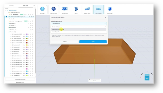
Choose Input Method expanded: Constant Vector, Flow Direction Point Map, and Import from file.
- Constant Vector applies one direction and one magnitude across your entire envelope. It's the simplest option, and the best place to start if you just want to see what shape Flow Direction creates.
- Flow Direction Point Map lets you pick different points on your envelope and assign a different direction to each one, for cases where the flow needs to vary across the part. When multiple points of flow direction are assigned, a smooth gradient of flow direction will be mapped based on the defined points, which will define the flow direction at different locations.
- Import from file brings in a ready-made point map from a CSV, handy if you're working from a pressure map, a simulation result, or any other outside data source. The CSV file format is like those for scatter vectors. It should have six or seven values per row. These values represent the X/Y/Z coordinate of the point, the X/Y/Z of the flow direction vector, and the magnitude, respectively.
Tip: If you already have a CSV point map from a simulation or pressure analysis, you can skip straight to Import from file instead of recreating those points by hand.
Setting a Flow Direction with No Magnitude
Magnitude is optional. With a value, it sets the flow weighting as a percentage. Left empty, the length of the X, Y, Z vector you entered sets the weighting instead. A weight of 70% means 70% of the infill surface will tend to follow the give flow direction while keeping it as a minimal surface.
To show the effect of weighting, we start with a case with weighting of 0%. To do that, set X, Y, and Z all to 0 and leave Magnitude blank, then click Apply.
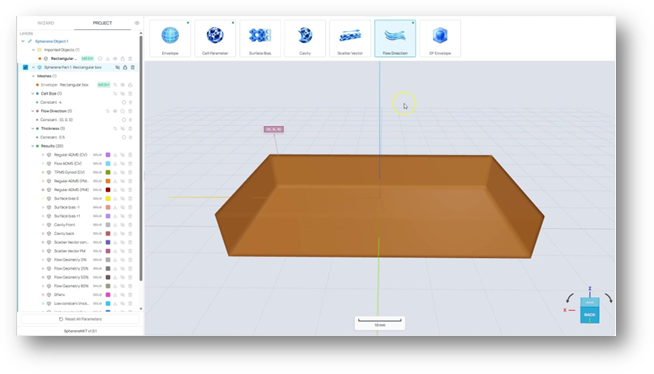
X, Y, and Z all set to 0, no magnitude. The applied value now reads Constant - (0, 0, 0).
Applying it brings up a quick confirmation, since defining a Flow Direction switches your Infill Type over to Flow ADMS automatically, if you did not pre-define it as Flow ADMS in the cell parameter.
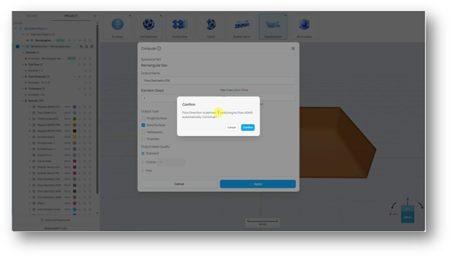
Confirm dialog: Flow Direction is defined. Switching to Flow ADMS automatically.
From here, click Compute like you normally would. Give the result a name, for example Flow Geometry 0%, and leave the rest at their defaults. Output Type still shows the four options you'd expect: Single Surface, Solid Surface, Halfspaces, and Chamber.
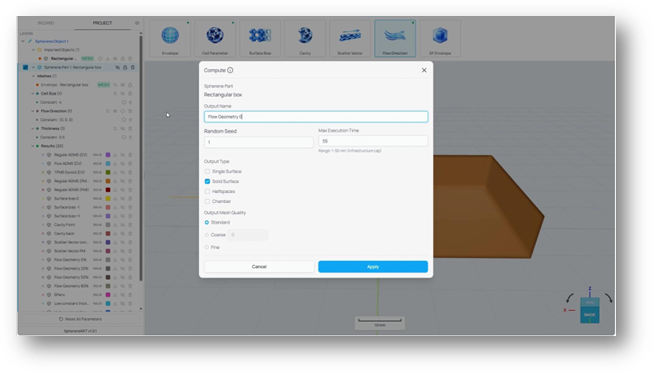
The Compute dialog. Output name set to Flow Geometry 0, Solid Surface selected under Output Type.
Run the computation, and here's what a Flow Direction with no magnitude looks like:
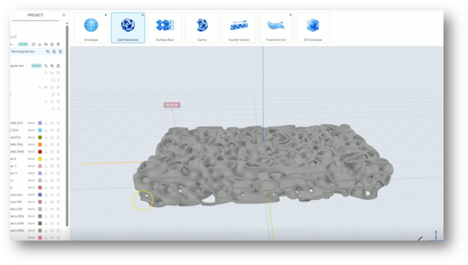
Flow Geometry at 0% magnitude. The structure has the organic Flow ADMS look without any directional preference.
Tip: Flow ADMS with 0% magnitude has no directional preference and therefore shows isotropy as the regular ADMS.
Adding Magnitude to Steer the Structure
Now for the part, Flow Direction is really built for: pointing the structure toward an actual fluid path. Say you have a fluid path that needs to travel from one side of your envelope to the other, along the X axis. Go back into Define Flow Direction, set X to 1, keep Y and Z at 0, and this time give Magnitude a value, say 25%.
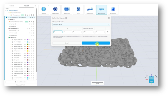
X set to 1, Y and Z at 0, Magnitude set to 25%, ready to Apply.
Apply, compute, and you'll see the difference right away compared to the 0% version. The structure is noticeably stretched along the X direction now.
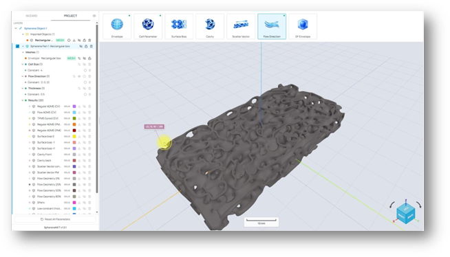
The result at 25% magnitude in X. Already visibly directional preference compared to the 0% version.
Pushing the Magnitude Further
Increase the magnitude and the stretching effect keeps building. At 50%, the structure pulls even further along X.
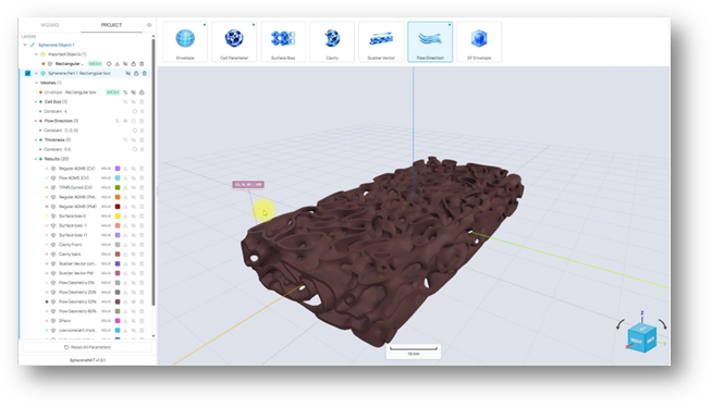
At 50% magnitude, the structure shows noticeably more directional preference along the X direction.
Push it all the way to 80%, and the effect gets pretty exaggerated. It's a useful reference point for just how far you can take this parameter, even if you'd rarely want to run with something this extreme in a real project.
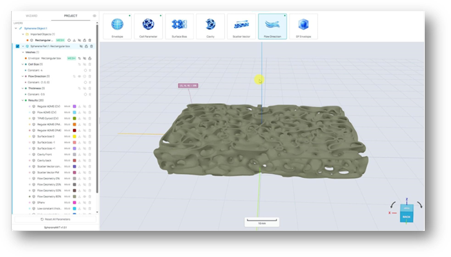
At 80% magnitude, the directional preference is far more pronounced. 80%-90% can be a good reference for the outer limit of the effect.
The practical upside of using flow directions is to generate a smooth infill surface following a predefined fluid path. The more your infill structure favors one direction, the less resistance flow encounters moving through it, which is exactly the point for heat exchangers, heat sinks, and cold plates. Be aware that introducing this directional preference will also change mechanical performance.
Tip: Higher magnitude of flow direction can introduce a stronger directional preference into infill geometry and therefore further improve the fluid performance. But a magnitude above 90% might not provide further improvement, as we constrain the infill surface toward a minimal surface instead of a tube.
Quick Reference
A cheat sheet for everything covered above, in case you just need a quick reminder later.
|
Step / Option |
What It Does |
Where To Find It |
|
Flow Direction icon |
Opens the Define Flow Direction panel. |
Icon row, right after Scatter Vector |
|
Choose Input Method |
Constant Vector, Flow Direction Point Map or Import from file. |
Define Flow Direction panel |
|
X, Y, Z fields |
Sets the direction of the flow direction. Its length represents the weighting of flow direction when the magnitude is blank. |
Define Flow Direction panel |
|
Magnitude (Optional) |
Sets the weighting of flow direction in %. If not blank, the length of the X, Y, Z fields will be ignored. |
Define Flow Direction panel |
|
Applying with no magnitude |
Switches Infill Type to Flow ADMS automatically, without introducing any directional preference. It is an isotropic geometry. |
Define Flow Direction panel |
|
Applying with magnitude |
Optimize the infill surface so that it follows the defined flow direction. The magnitude defines the percentage of the affected surface for this directional preference. |
Define Flow Direction panel |