
What Is a DF Envelope?
A DF envelope is a second, bigger object that you place around your main envelope. SphereneNXT first generates an infill structure within the defined DF envelope and then trims it by the defined envelope. This ensures that lattice can be generated in small regions or a larger surface contact area compared to the surface volcanos in regular ADMS. Be aware that those surface volcanoes grant ADMS good surface conformity. Using a DF envelope might lose the benefit of surface conformity, unless the DF envelope has the same shape and center as the envelope but with a size scaling proportional to the cell size.
When to Use a DF Envelope
This one's especially useful when your part has small regions or tight corners that the regular ADMS geometry just doesn't fill in properly. Rather than fighting those gaps, a DF envelope lets the internal lattice pattern flow through the whole part; tight corners included.
Tip: Remember that sphereneNXT isn't a CAD tool, so the object you use as your DF envelope still needs to be uploaded as a file, just like your main envelope. You can't sketch or model it directly inside sphereneNXT.
Setting Up a DF Envelope
Step 1: Open the DF Envelope Tool
In the ribbon, click over to the Surface tab and select the DF Envelope, right after Flow Direction. At this point your main envelope is just sitting there as a plain solid, waiting for the DF envelope to be defined.
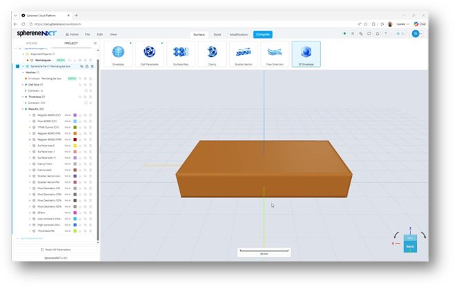
The DF Envelope tool sits at the end of the ribbon, after Flow Direction.
Step 2: Choose or Upload Your DF Envelope Object
Clicking DF Envelope opens the Define DF Envelope dialog. From here you can either pick an object that's already part of your project under Select Object or bring in a new one under Upload New Object.
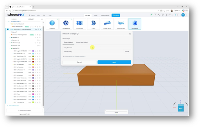
The Define DF Envelope dialog offers Select Object and Upload New Object tabs.
If you go with Upload New Object, clicking the upload area opens your regular file browser so you can pick a CAD file from your computer, the same way you'd upload any other object in sphereneNXT.
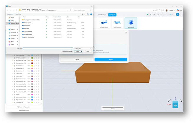
Uploading opens your file browser, just like uploading your main envelope.
Step 3: Make Sure It's Bigger Than Your Main Envelope
Once your object is uploaded and applied, take a look at it next to your main envelope. If it isn't bigger in every direction, sphereneNXT can't use it as a DF envelope yet, and you'll need to scale it up first.
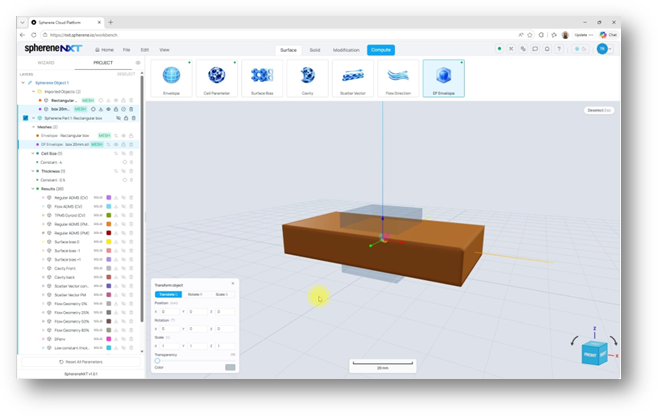
This uploaded box is still smaller than the main envelope, so it isn't ready to use yet.
Click on the object to activate it, open the Transform object panel, and switch to the Scale tab. Punch in scale values for X, Y, and Z until the object fully wraps around your main envelope. In this example, a scale of 3 on X, 2 on Y, and 1.5 on Z did the trick.
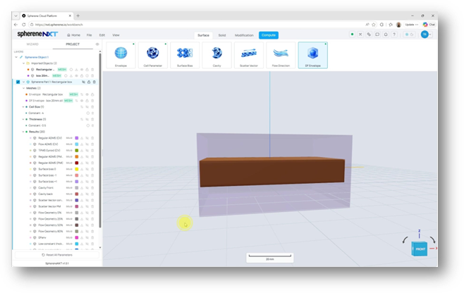
After scaling, the DF envelope now surrounds the main envelope in every direction.
Tip: It's fine if the DF envelope ends up close in size to your main envelope on some sides. That just means those sides of your final lattice will look more like a straight cut. What matters is that it's bigger everywhere, even if only slightly.
Step 4: Compute
With your DF envelope sized correctly, head to the top ribbon and click Compute. sphereneNXT starts generating the lattice, and you'll see a progress indicator while it works.
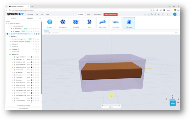
Computation begins once you click Compute in the top ribbon.
Understanding the Result
Once the computation finishes, hide the DF envelope object so you can see your part clearly. What you're looking at is a lattice shaped like the inside of that bigger DF envelope but clipped to the outer boundary of your main envelope.
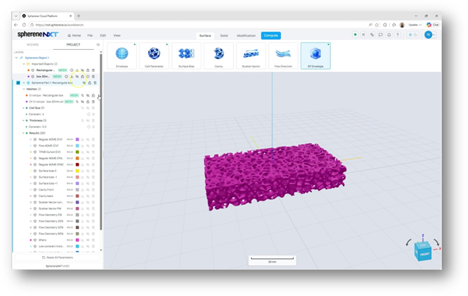
With the DF envelope hidden, you can see the finished lattice on its own.
If you look closely at the faces where your main envelope was close in size to the DF envelope, you'll notice those sides look flatter and cut off, almost like a cross section. The other faces show the full internal pattern of the DF envelope coming through.
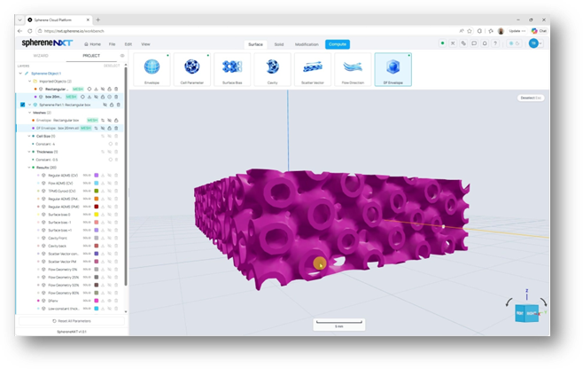
Up close, you can see the flatter cut-through faces alongside the open internal pattern.
That contrast is exactly what makes DF envelopes useful for sharp corners of your envelope. Wherever the internal pattern reaches, it fills in gaps that a regular envelope-based lattice would leave open.
Quick Reference
|
Setting |
What It Does |
Where to Find It |
|
Where to find it |
DF Envelope tool |
Ribbon, after Flow Direction (last tab in the row) |
|
Select Object |
Use an object already in your project |
Define DF Envelope dialog |
|
Upload New Object |
Import a new CAD file to use as the DF envelope |
Define DF Envelope dialog |
|
Size rule |
Must be bigger than your main envelope in every direction |
Check in the 3D viewer before computing |
|
Resizing |
Scale the object on X, Y, and Z |
Transform object panel, Scale tab (S) |
|
Compute |
Starts generating the lattice |
Top ribbon, blue Compute button |
|
Best used for |
Filling sharp corners of your envelope that regular ADMS geometry leaves open |
Any part with tight internal corners |