
What the Boundary Tool Does
You'll find Boundary as the first option in the Modification tab, next to Boolean. It creates a solid surface over a selected geometry, which is useful any time you need to cap a shape or seal off part of your structure.
Boundary works on top of a part that already has an envelope and cell parameters set up, with thickness allocated, just like every other sphereneNXT feature. Remember that sphereneNXT isn't a CAD tool on its own, so that envelope always comes from a CAD file you import.
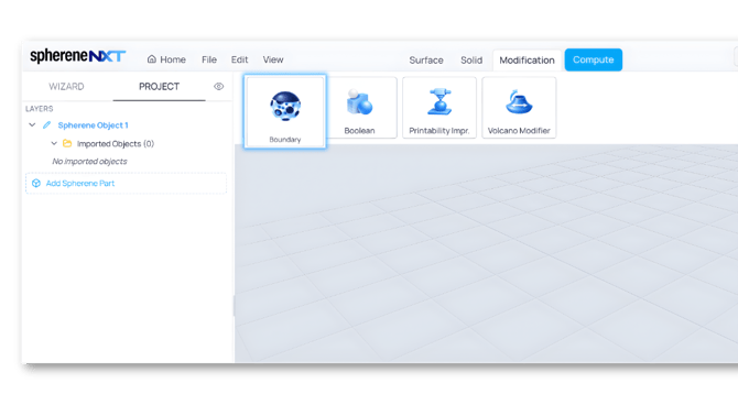
The Boundary tool sits at the top of the Modification tab, alongside Boolean, Printability Impr., and Volcano Modifier.
Opening the Define Boundary Dialog
Clicking Boundary opens the Define Boundary dialog, which gives you two ways to bring in an object: Select Object, for anything you've already imported and have hung in the scene, or Upload New Object, if you need to bring in something new.
There's one exception worth knowing about: for Boundary, you can also choose your already-selected envelope as the boundary object itself. Doing that creates a solid wall that wraps completely around your envelope connected with the infill structure inside.
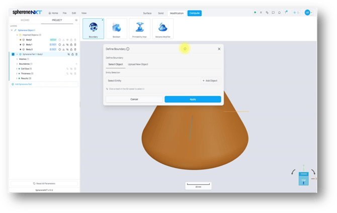
The Define Boundary dialog lets you select an existing object or upload a new one.
Understanding the Boundary Parameters
Once you add an object, the dialog opens four thicknesses and blends settings alongside the Front Chamber and Back Chamber toggles. The diagram below breaks down what each one actually controls, which is worth a look before you start typing in numbers.
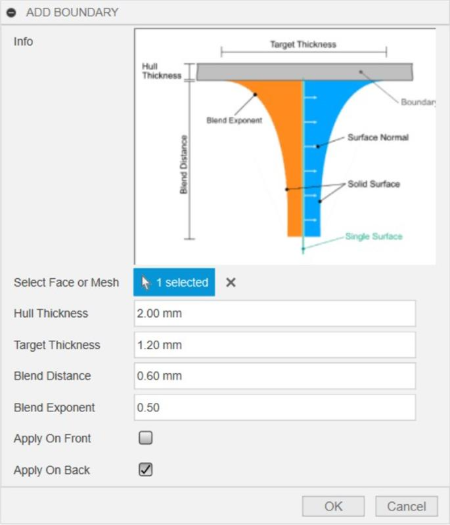
How Hull Thickness, Target Thickness, Blend Distance, and Blend Exponent shape the transition from a solid boundary into your lattice.
Hull Thickness is the thickness of the solid shell right at the boundary surface itself, the outer cap you see in gray in the diagram.
Target Thickness is the thickness of the bridge structure that blends the boundary solid wall and inner infill structure on the boundary surface.
Blend Distance sets how far that blending spreads within the infill structure, in other words, how much depth in the infill structure will be affected for this blending with boundary.
Blend Exponent shapes the curve of the blending region. It controls how gradually or sharply the thickness tapers off across the Blend Distance.
Apply On Front and Apply on Back (shown as Front Chamber and Back Chamber toggles in the current dialog) grant u selective control on closing only the selected chamber surface on the defined boundary surface instead of closing the whole boundary surface.
Tip: Hull Thickness and Target Thickness both need to make sense together. Set them wrong and the engine may not be able to build the structure at all, since it can't resolve a valid shape from the values you've given it. You might fail to generate a solid surface output if these boundary parameters are not correctly set up.
Building a Full Boundary Around Two Surfaces
Minimal surfaces divide space into two different chambers. When you add a boundary, you can decide whether to close both of them, sealing that part of your structure completely, or only close one and leave the other open.
For a first pass, add each surface as an object and leave both Front Chamber and Back Chamber toggled to Yes. Here, two single surfaces (no thickness of their own) were each added as boundary objects, with Hull Thickness set to 1.5 mm and Target Thickness to 3 mm.
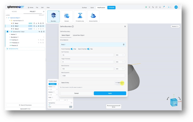
Front Chamber and Back Chamber toggles, plus the four thickness and blend settings, appear once you add an object.
Clicking Apply and then Compute builds the result. With both chambers left on for every object, the result (named Boundary full in the Results list) wraps a smooth, fully closed shell around that part of the structure.
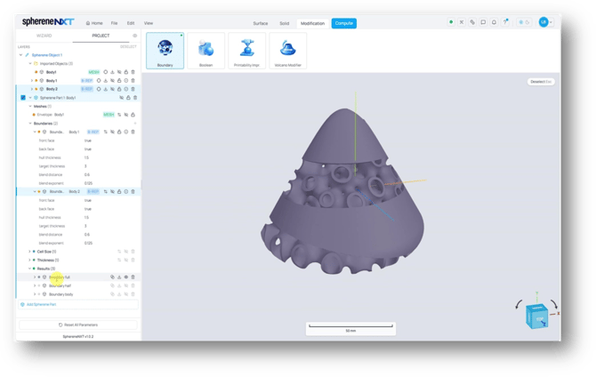
With both chambers left on for each surface, Boundary full wraps a smooth, closed shell around the whole structure.
Closing Only One Chamber Per Object
If you only want to seal off one of the chambers, turn off Front Chamber or Back Chamber to leave it open. For the next pass, Hull Thickness was increased to 5 mm for both surfaces, Back Chamber was turned off for the first defined boundary surface (leaving only Front Chamber on), and Front Chamber was turned off for the second defined boundary surface (leaving only Back Chamber on).
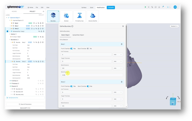
Turning Back Chamber off for Body 1 and Front Chamber off for Body 2 sets up a mixed boundary.
Recomputing without changing anything else produces a second result (Boundary half in the Results list). One chamber near the top closes off on the first defined boundary surface; the other chamber near the bottom closes off on the second defined boundary surface. That's how you close one chamber while keeping the other one open, using the same Boundary function.
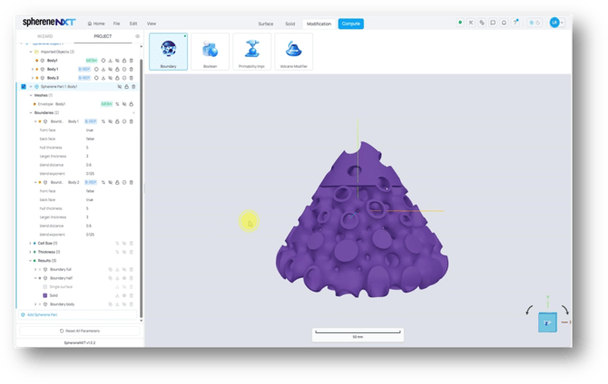
The mixed setting closes one side of each surface while leaving the other open, with a smooth transition between the two.
Tip: Front Chamber and Back Chamber are set per object, not globally. That means you can mix a fully sealed surface with a partially open one in the same boundary, all in a single Compute.
Using Your Envelope as the Boundary Object
Instead of picking individual surfaces, you can delete those boundary objects and choose your own envelope as the boundary object. Go back into Boundary, select Add Object, and pick your imported envelope. You'll need to make it visible in the layer list first before you can click it in the 3D viewer.
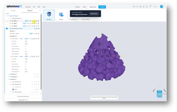
Placement mode lets you pick the envelope itself as the boundary object; make it visible first so you can click it.
With the envelope selected and your parameters set, Apply and Compute build a boundary that follows the entire shape of your envelope instead of just one or two surfaces (named Boundary body in the Results list).
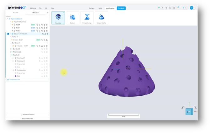
With the envelope as the boundary object, the result wraps a boundary shell around the entire shape.
Leaving one chamber unchecked here is only useful for getting a better look inside while you're checking the result. Keep both chambers on and you'll get a fully solid structure wrapped around your whole shape.
Applying Boundary to a Design: A Heat Exchanger Example
Here's the Boundary tool at work on an actual design, a two-fluids heat exchanger, where it makes both the design and the simulation setup a lot faster. In two-fluids heat exchangers, we need to ensure the two fluids do not mix with each other inside the infill. Therefore, for each inlet/outlet, we need to close the correct chamber near the inlet/outlet boundary to ensure the fluid will flow into the correct open chamber of the infill structure.
The envelope here is a design fluid space for a heat exchanger with a cold fluid inlet and outlet, and a hot fluid inlet and outlet, all imported ahead of time. Cell parameters use an ADMS structure, and the surface has already been thickened to 2 mm with the Thicken Surface tool.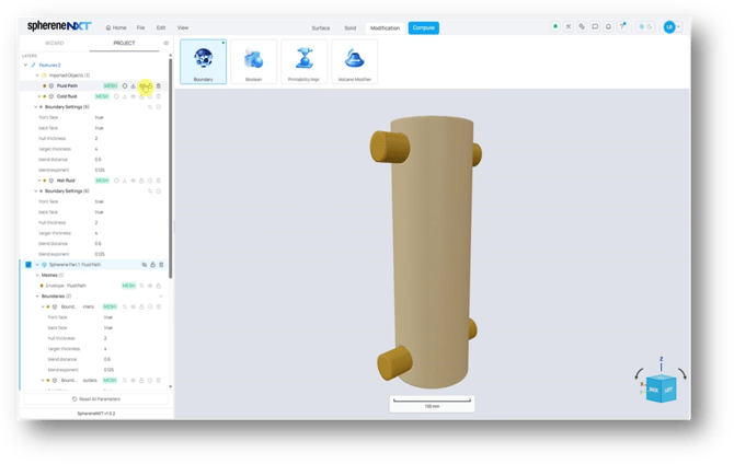
The envelope of fluid design domain, with its cold fluid and hot fluid inlets and outlets already imported.
Close the correct chamber at the inlets/outlets
In these two-fluids heat exchangers, we will inject two different fluids, each of them will flow into one of the chambers of the infill structure, that is separated with each other. We need to close one of the chambers at the boundary of inlets/outlets so that the fluids do not flow into the wrong chamber. Here for the inlet and outlet of one of the fluids, assign them as boundaries, where Front Chamber was turned on and Back Chamber off. And for the inlet and outlet of the other fluid, front off and back on.
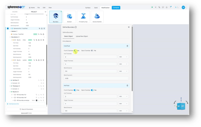
Front Chamber and Back Chamber are set independently for the cold and hot fluid objects, exactly like before, just with two paths to configure at once.
In addition to the solid surface, sphereneNXT also can output meshes of the two fluid chambers with correctly closed inlet/outlet boundary. To do that, you need to check Chamber under Output Type in the Compute dialog, alongside Solid Surface.
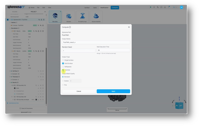
Checking Chamber under Output Type in the Compute dialog is what produces separate ChamberFront and ChamberBack regions.
The result will give you two separate regions, ChamberFront and ChamberBack, that should never touch each other. Looking at ChamberFront and ChamberBack results below, hot and cold flow through two separate networks that never touch, exactly what you want from a heat exchanger.
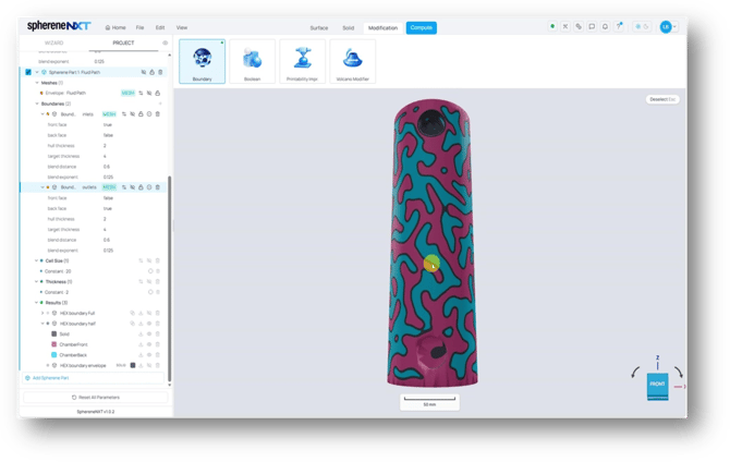
ChamberFront and ChamberBack overlaid, showing the hot and cold paths as two independent networks.
Tip: Front Chamber and Back Chamber still work per object here. Setting them oppositely on the inlet and outlet objects of two different fluids is what keeps hot and cold fluid on separate chambers instead of mixing.
Quick Reference
|
Step |
What It Does |
Where to Find It |
|
Add a boundary object |
Selects an existing surface or solid, or lets you upload a new one |
Modification tab > Boundary |
|
Add another object |
Assigns multiple boundary surfaces at a time |
+ Add Object |
|
Set Hull Thickness |
Sets the thickness of the bridge structure that blends the boundary solid wall and inner infill structure on the boundary surface |
Define Boundary dialog |
|
Set Target Thickness |
Sets the thickness of the bridge structure that blends the boundary solid wall and inner infill structure on the boundary surface |
Define Boundary dialog |
|
Set Blend Distance |
Sets how much depth in the infill structure will be affected for this blending with boundary |
Define Boundary dialog |
|
Set Blend Exponent |
Shapes the curve of the blending region |
Define Boundary dialog |
|
Toggle Front / Back Chamber |
Chooses the surface of which chamber gets closed off |
Define Boundary dialog, per object |
|
Turn on Chamber output |
Outputs the results of separate ChamberFront and ChamberBack regions |
Compute dialog > Output Type |