
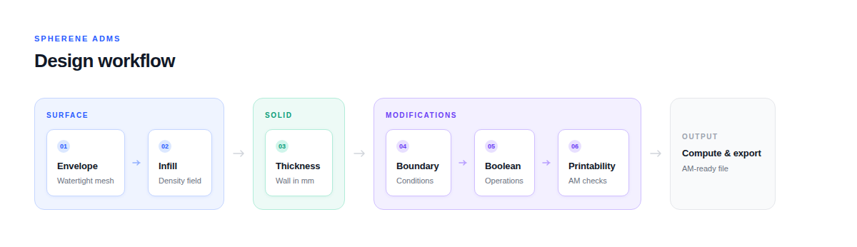
Spherene turns the interior of a part into a precision-engineered structure. Instead of filling a volume uniformly or relying on a repeating pattern, it generates geometry that responds to your part's actual shape, loads, and functional requirements. The process is straightforward:
Step 1: Define your envelope
Everything starts with an envelope. You bring in the outer shell of your part, and that closed volume becomes the envelope. Think of it as the container that Spherene will work within. The envelope can be any complex 3D shape, a satellite bracket, a midsole, a heat exchanger housing, or a structural connector. Spherene conforms to it without simplification.
Step 2: Tell Spherene where material should go
Once the envelope is set, you define how material should be distributed inside it. This is controlled through the density field. A single value fills the volume uniformly. Multiple values across the part create a gradient: denser where stiffness is critical, lighter where it is not.
For example, a crash absorber designed for aerospace might carry high density near attachment points and progressively lower density toward selected crush zones, so it deforms in a controlled, layer-by-layer sequence rather than collapsing unpredictably.
In a footwear midsole, the same principle applies in reverse: softer zones under the arch, firmer support under the heel, all generated from one continuous internal structure.
Step 3: Refine the geometry for your application
Beyond density, Spherene gives you direct control over how the internal surface behaves.
Surface bias shifts the geometry along its own normal, changing the ratio between the two internal chambers. This lets you tune how the structure responds to compression versus tension without changing its overall mass.
Scatter Vector stretches the geometry in defined directions, introducing intentional anisotropy. If a part carries load primarily along one axis, the internal structure can be aligned to that path, giving you directional stiffness exactly where you need it.
Cavities push spherene geometry away from defined zones, leaving room for inlets, outlets, channels, or other features that need to remain open.
For thermal applications, Flow ADMS replaces standard ADMS with a flow-optimized surface geometry. Combined with Flow Direction, it aligns the internal structure to defined fluid paths, reducing pressure drop and improving heat transfer efficiency in heat exchangers and cooling components.
Step 4: Set wall thickness and output
Once the structure is defined, you set the wall thickness of the surface. This converts the surface into a manufacturable solid geometry. Wall thickness is based on the Density Reference Thickness (DRT) by default but can be varied spatially if a Thickness Field is applied.
Spherene outputs a mesh that is self-supporting by design, meaning it minimizes the need for build support in additive manufacturing. This is not a post-processing step; it is inherent to how ADMS geometry is generated.
Step 5: Export and manufacture
The output mesh goes directly into your manufacturing workflow: into a slicer for additive manufacturing, or into your FEA environment for validation. Because Spherene generates geometry that correlates closely with simulation, what you model is what you get. The ESA OSIP validation demonstrated less than 5% deviation between simulated and physically tested natural frequencies on an AlSi10Mg satellite bracket.
What this looks like in practice
The same process applies across very different industries:
- An aerospace engineer designs a lightweight bracket using a gradient from dense attachment zones to an open core, then validates it digitally before printing in titanium.
- A product designer creates a ski boot liner with zones of varying stiffness, all within a single continuous structure that prints without support.
- A thermal engineer builds a compact heat exchanger where the internal geometry directs two fluid streams through separate labyrinth networks, reducing pressure drop by more than 20% compared to a gyroid-based equivalent.
In each case, the workflow is the same: define the space, set the material distribution, refine the geometry, and export a part that is ready to manufacture.